- Buzz are a very loud and anoying sound for ~1 second.
- The time between "buzzes" change.
- Run on <>
- Easy to hide
- Be michevous!
- Buzzer @ 3.2Khz
- Counter Shift Registers - Mouser no longer stockes these.
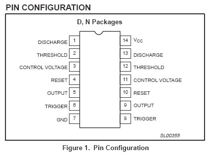
- 556 Timer
- 8 input Nand Gate
- PLD - you should find this yourself.
The values that the wesite will give you are:
- 0.00K Ohm - R1
- 72.0K Ohm - R2
- 10uF - C1
The next thing that happens is we need to look at a 14 bit ripple counter. I used the "MC14040BCP". The basics of this chip are power on 16, ground on 8. From pin 3 on the 555 timer, run the input to 10. For right now thats all we need to go.
Okay so since I have already done it and ran into a problem. The pizo electric speeker requires a clock. Well we are screwed at the moment, because out clock is being used for the ripple counter. So we need another one. Well, this is an easy fix thanks to the great people that make IC's. They have something called a 556 timer. This is a 555 timer with 2 timers that work independently of each other.
After doing some research (and some help with a few friends) I found that a pizo electic speeker is increadibly loud at 3Khz. And the pizo buzzer that I found is very good (and speched at 3.2Khz). Here is the scematic for the 556 timer. So we will have to use this from now on.
Okay the next thing we need to do is get an 8input NAND gate. The output from the NAND gate will be connected to the 3KHz reset pin. Okay so I am going to just put out the scmatic here and you should be able to put it all together. If you have any guestions feel free to email me, ethankhall (at) gmail (dot) com. Sorry just want to keep the spam down.

From here I will go and talk about how I am going to make it better with GAL device, this requires a Dataman. This is an expensive piece of equipment ( I dont know why though).
Special Thanks:
Patrick Wright, Matt Barton
hehehe. :) I like.
ReplyDelete